Stabilizing the laser power of a solid-state laser diode instrument
The importance of lasers nowadays arose from their wide range of applications including
medicine, manufacturing, research, communication, etc. One major issue associated with
lasers is their sensitivity to the surrounding environment parameters such as
temperature, humidity, and mechanical vibrations. Minor changes in these parameters
manifest in fluctuation of the laser's power which affects the final processing
outcomes. Hence, stabilizing their output powers is critical to guarantee a precise
and highly controlled process.
Even though laser devices come with internal mechanisms such as cooling systems to
enhance stability, it is not enough because variation in the external surroundings
affect these internal mechanisms which impact the final laser stability.
This article demonstrates how I stabilized the laser's power of a solid-state laser
diode, for research purposes. The active stabilization method is used via the
implementation of feedback signal technique.
Apparatus required
In this section, I will introduce you to all the apparatus that I used and the function of each one of them.
- Diode-pumped Solid-state laser diode (980 nm) unit produces power > 2.5 W, used as the laser source.
- Ocean optics USB2000+ spectrometer to monitor the laser intensity.
- Convex lens to focu the laser beam.
- Quartz slide to split the laser beam into main and feedback beams.
- Stepper motor and strip of aluminum sheet to control the laser intensity by blocking/allowing part of the laser beam.
- Power meter to measure the feedback laser power and send readings to the microcontroller (Raspberry Pi).
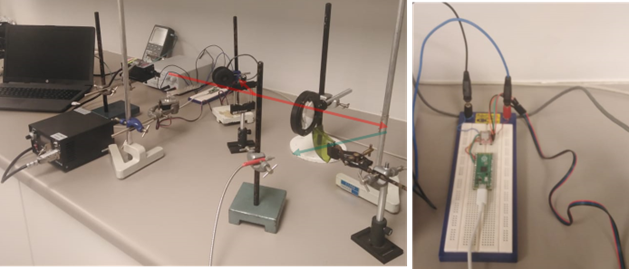
- Raspberry Pi Pico for controlling the stepper motor with strip of the aluminum sheet, the raspberry Pi is fixed on an electronic board.
- Motor drive IC, which takes signal from the Raspberry Pi, amplifies it, and turn the stepper motor.
- DC power supply to power the electronic control circuit (Raspberry Pi plus Motor drive IC).
- Two PCs, one for the Ocean optics USB2000+ spectrometer to monitor the laser intensity, and the second PC for the power meter to read the feedback laser power. Note that we could have used only one PC for monitoring the laser intensity via the Ocean optic spectrometer and the feedback signal power via the power meter. However, due to licensing issues which restricted the use of software on a specific PC, we were forced to use both PCs.
- Stands for holding the optical components and devices.
How the system works
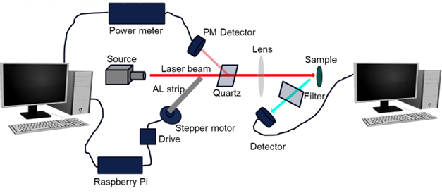
In this section I will explain how the whole system works and the role of each component. We use the schematic below which represents the real setup for explanation

Firstly, the laser source produces a laser beam that passes near the AL strip and then
through a quartz plate. We will come back to the function of the AL strip and how it
works shortly. The quartz plate reflects about 5% of the laser beam back while the rest
passes through the convex lens and focuses on the sample. The quartz works as a beam
splitter and due to its high stability, the ratio between the reflected and passed laser
power (5: 95) remains constant. If we know the intensity of the reflected laser then we
know the intensity of the passing laser beam as well. A power meter is now used to
measure the intensity of the reflected laser which we now call feedback/control signal.
The feedback signal which represents the laser power is continuously monitored and the
value is sent to the PC on the left.
The second part of the control is the electronic circuit which reads the feedback signal
power and decides to turn the aluminum strip left or right by using the stepper motor.
I have programed the Raspberry Pi Pico using Python so that it keeps an eye on the
feedback signal power, and if the power is below certain (pre-defined) value, the
stepper motor turns the aluminum strip to the right which allows more laser beam to pass
through, otherwise blocks parts of the laser beam. Hence, the laser power/intensity
beyond the quartz plate remains stable and unchanged. Note that a predefined laser
power must be inserted in the Python script before starting any measurement.
Nevertheless, the laser intensity requires adjustment in relation to the aluminum strip
position so that it is not too open or closed.
On the right-hand side, the stable laser beam is focused on a sample, and both the laser
and sample emissions are measured using an Ocean optics USB2000+ spectrometer. The
filter is used to attenuates the laser intensity so that the detector is not damaged.
The sample part is what this setup is used for, but you can ignore it since this
article is only about the laser stability mechanism. The following photo depicts the
setup in real life

The following figures show the laser intensity monitored for about 24 hours before and
after the implementation of the stability mechanism. It can clearly be seen on the
right-side figure, before the stability mechanism implementation that the laser
intensity is unstable due to surrounding environment which is high likely temperature
and humidity fluctuations. The left-side figure proof the effectiveness of the stability
mechanism which resulted in a very stable laser power/intensity.
Remember, there is always a different way to stabilize the laser power, depending on
many factors such as application, type of laser, etc.
